151CMQ... Series
4
Bulletin PD-2.252 rev. B
05/02
www.irf.com
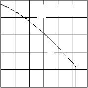
Fig. 7 - Max. Non-Repetitive Surge Current (Per Leg)
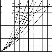
Fig. 5 - Max. Allowable Case Temperature
Vs. Average Forward Current (Per Leg)
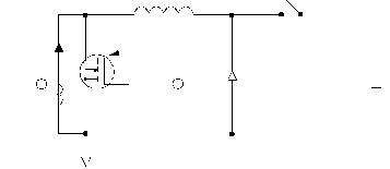
Fig. 8 - Unclamped Inductive Test Circuit
Fig. 6 - Forward Power Loss Characteristics
(Per Leg)
0
10
20
30
40
RMS Li mit
50
60
70
80
0 102030405060708090100110
DC
Average Pow
er Loss - (W
atts)
Average Forward Current - I (A)F(AV)
D = 0. 08
D = 0. 17
D = 0. 25
D = 0. 33
D = 0. 50
80
100
120
140
160
180
0 20406080100120
DC
Al l owabl e Case Tem
perature - (°C)
Average Forward Current - I (A)F(AV)
151CMQ
R (DthJC
C) = 1.0°C/W
1000
10000
10 100 1000 10000
FSM
Square Wave Pulse Duration - t (microsec)p
Non-Repetitive Surge Current - I (A)
At Any Rated Load Condition
And With Rated V AppliedRRM
Following Surge
FREE-WHEEL
DIODE
40HFL40S02
CURRENT
MONITOR
HIGH-SPEED
SW ITCH
IRFP460
L
DUT
Rg = 25 ohm
Vd = 25 Volt
+


发布紧急采购,3分钟左右您将得到回复。
相关PDF资料
153CMQ100
SCHOTTKY RECT 100V 150A D-60
153CNQ100
SCHOTTKY RECT 100V 150A D-60
155CMQ015
DIODE SCHOTTKY 15V 75A D-60
1N5711W-7
DIODE SCHOTTKY 70V 333MW SOD-123
1N5711WS-7
DIODE SCHOTTKY 70V 150MW SOD-323
1PS181,115
DIODE 80V 215MA HI-SPEED SC-59
1PS184,115
DIODE 80V 125MA HI-SPEED SC-59
1PS226,115
DIODE 80V 125MA HI-SPEED SC59
相关代理商/技术参数
151CMQ050
制造商:IRF 制造商全称:International Rectifier 功能描述:SCHOTTKY RECTIFIER
151CNQ035
制造商:未知厂家 制造商全称:未知厂家 功能描述:
151-D05D
制造商:LG Corporation 功能描述:TRANSFORMER,STAND-BY
151D10104
制造商: 功能描述: 制造商:undefined 功能描述:
151D106X9020B2
制造商:Sprague/Vishay 功能描述:NONPOLAR AT610X020
151D116X0010X2
制造商:Sprague/Vishay 功能描述:NONPOLAR AT611X010
151D116X9050W2
制造商:Sprague/Vishay 功能描述:AT611X050 SEE NOTES
151D117X0010Z2
制造商:n/a 功能描述:SEE: T111D117M010AS
